Friday, May 17, 2024

The Companion Status

I have not heard from the fellow who volunteered to revamp the site. So it will remain as is, imperfect.

No one has submitted a new article since 2023.

The mods of the LD forum have reverted to answering the same questions again and again. There is no chance of new mods.

DM - May, 2025


Sunday, June 4, 2023

Replacing the Generator Fuel Pump

The long saga with my generator refusing to run longer than a few minutes is finally resolved. 

How the generator got in this condition is worth reviewing.

Since we have owned our LD, we have been on the road over half of each year so the generator was used as we eschew campgrounds with hookups. However, camping wo popcorn is way too primitive. [It’s not the hookups, we mind, it’s that the people that frequent these CG’s are just not “our people”. We have little in common with them. Concrete Campers and Boondockers are two different species]

At home, I run the generator with a load for 45-60 minutes a month.
Using the generator, keeps the gasoline in the carburetor from turning to varnish and gumming it up.
A health issue prevented me from doing the monthly exercise for well over six months.
In hindsight, had I thought about it I could have drained the carburetor. But that bypasses the other reason for exercising the generator.

Not using the generator is true for most LD’s. I suspect few do a monthly exercise. (*) So there should be a lot of gummed up carbs out there. Mine sure was after months without use.


Symtoms:
It would run for 3-4 minutes, constantly surging. I could see the butterfly valves rapidly swinging back and forth. It would throw a 3-3 code which is not a documented code.

Trying to figure out the problem, I entertained all sorts of suggested remedies. Few had any bearing on the issue. One was too drain some oil out of the crankcase. Really! I noted the fuel pump supplied seemingly copious quantities of gas. After cleaning the carb bowl of varnish (https://www.youtube.com/watch?v=6053Qti0OLU&t=1102s) it ran a few minutes longer. I finally bit the bullet and ordered a Onan (not a knock off) fuel filter and pump. ($200+) I then embarked on the extremely PIA procedure to replace them. (https://www.youtube.com/watch?v=jlrHl0OWSZU)

Worth doing:
1)  Put colored tape on the wires you disconnect so you know where they go.
2) Take pictures before you take it apart.
3) Try see where the wires will have to be tucked back in as you carefully and slowly remove the control board. I failed this.

When I got it put back together, I primed it and it fired up and ran perfectly. Bob’s your uncle.

Be sure and tighten the fuel supply line from the pump before replacing the control board. I failed this and got to remove the board to access the fuel line. Also check for any other fuel leaks.


* If you see an aged RV advertised with low hours on the generator, figure it does not work. A 10 year old LD, should show 120 hours minimum on the meter.

Monday, May 22, 2023

Sewer Hose Storage

Dealing with sewer hose can be intimidating for a new RV'er. Lazy Daze comes with a tube for storing the sewer hose and the sewer hose supplied has no connector on the busy end. It felt gross to dip my hose into the dump station sewer opening, so I found an alternative solution. I bought Prest-O-Fit 1-0203 Blueline Ultimate Sewer Kit on Amazon. For  about $50 you get two 10 foot hoses and and an elbow connector that fits various dump station sewer openings, including the threaded ones. The Prest-O-Fit connector is narrow - same diameter as the hose itself, so it slides into the storage tube easily. On the other side (the one that hooks up to the RV), I have installed Duraflex 24649 45° Angle Hose Adapter using 3" adjustable duct clamps. The 45° hose adapter is small enough to allow the store tube cover to close neatly. I carry one 10 foot hose in the tube, and the second one as a spare in the front compartment on the left side along with the elbow connector stored in a ziplock. I rinse elbow connector after usage and overall I am pretty happy with the setup.


Wednesday, May 10, 2023

End Caps

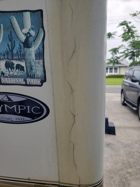
These pictures of cracked end caps are examples of the worst case I have seen. They show years of neglect and ineffective amateur repairs.


The first picture shows several hair line cracks that could be cured with 3M 5200. I might enlarge the cracks with a Dremel tool before filling them. The takeaway is that they are large enough and numerous enough to allow water into the pine wood that the cap covers. That wood is structural. It holds the window. Also water will find it's way to the floor and you will never know it until it too late.

Curious about this picture is that the cap is a dingy brown. The 5200 is white like the AL next to the cap. Why is the cap brown? Has there already been substantial water damage that has discolored the cap?


Same rig, drivers side. It looks like someone tried to patch the crack with some sort of tape. I would guarantee the wood behind the cap is rotted. Note the WA tag - Hurricane Ridge is a super wet area of the state.

I would say this rig needs the cap replaced, if caps are still available. Once removed rebuilding the wood frame would be possible. Joining new wood to the existing remnants with West System epoxy. Inside surgery might also be required.

If an new cap can not be obtained, I would cut away the damaged area of the cap  leaving the edges for a mold and rebuild with West System epoxy and FG mat. Gflex with a filler added may be the ticket. [West 105 would certainly be the best choice, but would be rather expensive for such a small project]


Puzzling to me is that a crack on the cap seems to extend to the AL skin. It extends all the way to the stripes. Could part of the AL have been patched with FG?

This is a rig to walk away from.

Oxidation /Electrolysis on Aluminum Sides


The bumps that are on the aluminum sides of some Lazy Dazes, that people call bumps, rust, or corrosion is oxidation (also often referred to as electrolysis).

It is caused when water/moisture gets between the aluminum and the coating/paint on the outside of the aluminum.  

This happens because the paint/coating becomes permeable over time as the aluminum flexes and is stressed.  It has been seen on LDs never exposed to sea air or chemicals used on snowy roads, it has been seen on LDs just a few years old,  but most often it is on older LDs.

Having one or even many of these does not mean that water got into your LD wall - that problem comes from other causes.

Once electrolysis starts, it will continue even if there is no more moisture/water (eg in a desert inside a garage), and the bumps just get worse.

To fix the bumps the basic steps (details below) are to sand the the area down to bare metal.  The area needs to be cleaned as a prep to the next step.  Then any damage to the aluminum needs to be fixed.  Then just primer and paint.  

Airlines use Scotch-Brite Surface Conditioning Discs (a drill attachment) to sand the affected area.  Make sure you get all the affected area (go a little bigger than the bumps until you see good paint-aluminum adhesion).

We found conditioning discs at Home Depot.

The material inside the bump typically crumbles - like chalk would.

Once you have the area sanded you will see different situations.

For a newer bump you will see the aluminum looks fully intact (no holes or indentation).

You may see no holes but an indentation, this needs to be patched back up to level (details below).

If the bumps have been there a while (larger) you will likely see a hole once you sand it down.  The hole can be the size of a straight pin body or larger.  

The oxidation leaves behind a fine powder.  If you have a hole, that powder will be in the hole and as part of the cleaning you need to use compressed air (canned air works fine) to blow out any dust you can so the repair material will stick.  Throughly blow it out - past where you think you have it all out (speaking from experience here).

You can check if the hole let water into the wall - depends a lot on your climate (rain, humidity) and size of the hole that penetrated fully through the aluminum.

If the hole is very tiny, it is  unlikely water got into the wall but the only way to check is from the inside.

If the hole is larger (I have not seen any larger than 1/16” but of course they could get larger), you can check by poking inside the hole to check for wood rot.  I highly suggest knowing how it feels to poke (with metal) new pine wood (soft wood and softer than the older wood in your LD) so you know if the wood inside the siding hole is rotted or not.  But personally if I felt wood rot I would address that from inside the LD unless I was taking that siding completely off for other reasons.

To repair the damaged aluminum - an indentation or a hole - even a tiny one, 

Use JB Weld brand epoxy - this is what commercial aircraft uses.  There is a lot of JBWeld, make sure you choose one that clearly say it works on aluminum (stated on back of package typically).  

Prep as the JB Weld says to.  The JB Weld we used hardened quickly but it also sanded level very easily.  It was also easy to scrap level with a plastic putty knife which almost completely eliminated any need to sand.

When that cures, primer and paint - most LD owners use automotive primer paint.

Do not leave the aluminum bare - this will just create more oxidation.


Friday, January 13, 2023

Repairing End Caps

Now that the mothership has closed, you can not remove/replace end caps. (They will be destroyed during removal) So resolving leaks will require a different tack.

After many months of worry and reading up on how-tos, I finally decided to take on sealing the end caps yesterday. I have done numerous caulking jobs in the past, so I’m not sure why I was so nervous about this project, other than the fear the caps could crack or break.

So I printed out the LD Companion steps, read and and re-read them, got all my supplies together and set off from home. The rig is parked remotely, so I had to make sure I had everything with me before I left. I didn’t do too badly in this regard, I only bought a caulking gun.

To the supplies list on the Companion, I would only add or confirm what helped me:

•   Air compressor (to blow out any debris)
•   10oz tube of 5200 Fast cure (much more than enough, but I didn’t know at the time how much I’d need)
•   Painters tool & a plastic putty knife
•   A caulking gun (depending)
•   Stainless steel screws & drill
•   Brake cleaning fluid – maybe overkill, since I also used a compressor, but for $3 more, why not?

I ended up not using the DAP 3.0 crystal clear sealant on the colored area - I wasn’t troubled by the thin line of white that the 5200 left in the blue sections. I brought clamps, thinking I could use them at least up near the cab, but there’s no way to do that, so I went with stainless steel screws of various lengths, ¾” to 1.5”).

The prep work was pretty easy, I started on the driver’s side end cap next to the cab because there was a good amount of separation which gave me space to work and see what was underneath. I didn’t get it all the sealant but I got enough so the new stuff would adhere to the surfaces. I used an acetone-soaked cloth wrapped around a putty knife to clean out the area as good as possible and finished it off with the brake cleaning fluid that’s mentioned in the Companion. [Ed. The best clean up is MEK. MEK is now available for retail sales in many states. I notice that ACE hardware is now selling an MEK substitute. Never heard of using brake fluid.]

After I cleaned the first area, I went to the rear end caps which is what I had been afraid of for so long. I did the same cleaning steps, using a razor knife, putty knife, acetone soaked putty knife and scraped as much as I could. I didn’t think to have a rag handy to catch drips when spraying the brake cleaner so it ran down the side of the end cap and appeared to stain it. I wiped it off as quickly as possible with acetone and a rag, but probably not fast enough. Other than that, prep work went well.

Now I was nearly ready to start with the 5200 sealant. I had gone through the steps in my head because I wanted to work as efficiently as possible. Plus it was hot and the layers of nitrile gloves were dripping sweat pretty early in the process. It was about this time I realized I had left the caulking gun at home.

With my new $5 caulking gun, I taped off my work areas (I could have done this before I started but didn’t). On the front end cap I pre-drilled two holes thinking they would be enough to secure the end cap. I underestimated by 4 screws. I wish I had thought through their placement sooner, but I was already in progress with an open tube of sealant.

I moved to the back and began work on the area that gave me the greatest amount of fear. It actually didn’t go too badly at all. I had a spot up at the top of the coach that had considerable separation and I was able to fill it and pop in a screw. I’ll cover it with Eternabond next. I added screws as shown in the photos – I hope the LD community isn’t too horrified at how I defaced her with the screws. In my defense, there were already screws in other parts of the end caps, so I wasn’t the first one to do this. Not sure if this was done by the factory when it was built or sometime thereafter. Instead of removing the screws, I think I will be painting over them once I can get some matching paint. Here’s hoping they don’t crack the end caps, which may be the reason that I should remove them and fill in the holes. Any thoughts from the community on this are appreciated. I sank the screws in (not too snugly) only after I had filled the gaps with sealant to ensure that they would have sealant on the threads.

I went back today to take a look at it and I don’t feel too terribly about it. I’ve included some before and after photos of how it looks.

Long story short, it’s not the most professional-looking job, but it should stop water intrusion, which is the goal. I think I’m satisfied enough with the result. I probably wouldn’t do this on a 90 degree day either, but I was also wanting to get the project checked off the list.

I used a good deal of 5200 on the front end cap, if I hadn’t needed to do this, I would have gotten the small tube. I think I only used 2/3 of the 10 oz tube, which cost $25. All in all, a pretty low-cost, not-overly complex project.


Sunday, October 16, 2022

Clearance Lights

There are two styles. Round and rectangular. The latter was used in at least 2007 and forward both front and rear. The author of this article had a round lens on a 2000 model. The round style is a Peterson 102-15 series. The assembly is out of production. The lens is available from Fox Tail Lights. PM 102-15 A or R.


The front 5 clearance lights on my 2000 Rear bath were cracked and falling apart. Over time the housings will eventually crack and the screws used to install the lights will corrode. On my lights, the screws have so corroded a screwdriver would not be used to remove them, and some of the heads broke clean off.

Water Intrusion is a certain issue when the clearance lights get this bad, I can’t say after removing and replacing the lights that zero leaking had occurred, but I have zero signs of water damage on the interior paneling and it does look like lazy daze sealed some of the wires/screws from the inside and outside when the front cap was assembled.

The procedure is as follows:

1. Remove screws holding old clearance light in place, if the head cannot be accessed with a screwdriver I used “engineer screws extractor pliers”…they can be found on Amazon and are an absolute godsend with working with rusty screw heads.

2. Slowly break apart the old light housing around the sealant wiring, there is a significant amount of sealant so just cracking the housing in half (after snipping the wires) is necessary.

3. Pry as much old sealant from the wires as possible, on 4/5 of my lights it appears the wires have sealant applied from the opposite side of the end cap, so while there is zero chance of pulling some slack, there also was no chance of the wires going back and getting lost within the cap.

4. Take the new light fixture and drill/ream whatever sized hole was necessary to fit the wiring through, this varies as the lights have 2 butt connectors and a few strands connected, the does not matter how much of a hole you drill, as long as it is all sufficiently bedded in sealant.

5. Apply sealant behind the new fixture and around the wiring, and press the fixture into place. I screwed the fixture down with #8 screws at first but they didn’t hold as tight as I preferred, I swapped to #10 and actually used a #12 on one of the mounting holes that were stripped from me removing the old rusty screw.

6. If you are using incandescent bulbs polarity does not matter, so I attached 1 wire to the light housing/mounting screw with a ring connector, and attached the black provided wire with a waterproof twist-on butt connector. 

Using a twist-on butt connector is likely the least reliable way to make this connection, but I choose waterproof (greased) versions. This allows me to remove the connector in the future if need be, since there is virtually zero extra wiring to work with, I avoided a permanent crimp connection. Likewise, because everything is so thoroughly packed in the fixture, very little movement will occur when going down the road.  These wiring decisions could allow me to remove and replace the fixture again in the future without needing to cut the wiring.

7. Once all connections were made, inspected to ensure sufficient sealant is applied, then follow up with a layer of dielectric grease over the stainless screw heads, into any open wiring splices, and into the bulb socket. This step could double the life of these connections in regard to corrosion resistance.

The only concern I have with this whole setup is the lack of adequate water draining, the fixtures have a drain hole but it will not function once they are installed, and adding a drain hold in the ideal location would likely result in weakening of the overall fixture. I will monitor how much water enters and stays within the fixtures over the long term. Water allowed to stay in the fixture will freeze in the winter and cause cracking.

I have attached photos of the fixtures I purchased. They were surprisingly difficult to source in the required diameter, but these are the exact diameter as the Peterson manufacturing 100 series and the mounting screws fit up perfectly, the only modification required was to drill holes large enough and in the correct locations to bring the wiring through.

I would rate the difficulty of this repair pretty low on the spectrum, however, it is relatively tedious.


I would use LED bulbs. Color emitters to match the shade of the lens.  These are available from Super Bright LED.

Red:  194 LED Bulb - 5 SMD LED Tower - Miniature Wedge Base | Super Bright LEDs   

Amber:  194 LED Landscape Light Bulb - 5 SMD LED Tower - Miniature Wedge Retrofit -


They use less power, the bulb doesn't turn black as the tungsten filament coats the inside of the glass, and the color stays true if the lenses fade. 

Wednesday, August 24, 2022

Swapping the factory Parallax converter for a PD4655 converter

This applies to all PD models

Replacing the DC fuse board may be difficult due to the shortness of the 6-gauge wires from the coach batteries. The Parallax DC board is sufficient for powering the DC circuits in the coach. so replacement is not required. If the wire lengths permit installing the new DC board it will give you two more circuits plus the function of a blinking light showing which fuse is blown. 

The “Charge Wizard” feature in the new PD system is not necessary to properly operate the new converter. However, it is useful for setting the charge rate to float for long-term storage.

The AC black, white & green wires from the PD 4655 converter go to the  AC breakers above. Just reinstall those wires where the Parallax AC wires were removed. The black (+) & white (-) DC wires from the left side of the converter board feed to the DC fuse panel in the locations where the Parallax DC cables were removed. Label the wires if you think you might get confused.


A close-up of the AC side connections and breakers. 
The black AC wire goes up to the AC converter breaker and the white wire to the lower buss bar & green wire go to the buss bar to the left (ground).


The black DC (+) wire attaches at the +UCC screw down terminal and the white attaches at NEG screw down terminal as shown below. If you are careful making these two wire attachments I don’t think you need to turn off the DC from the batteries. If you want, trip the in-line resettable fuse and remove the fuse from the solar panel. The orange wire with the fuse to the +UCC terminal is the feed from the solar panel. Once these two DC wires are attached, replace the covers and you are finished!


Ensure all wires are securely tightened. Even the DC wires that you did not remove if you did not replace the DC board. It's good practice to check tightness every year.

Mike Coachman 8/22


Monday, October 25, 2021

Storage Tanks and Dumping


Forget about the dump lights on the stove that are always wrong for the Gray and Black tanks. Cover them with black tape. They are NOT needed IF you will always use fresh water from the tank. [Don’t connect the hose to fresh water inlet]  Well, using the capacities for a mid bath made in the last 20 years, fresh water is about 60 gallons, the gray tank holds 40 gallons and the black tank just under 30. So a reasonable allocation of 60 gallons of fresh water can not fill two tanks of 40 and 30 gallons.

A couple taking a Navy shower every other day in the dry desert SW can go 5 to 7 days on 60 gallons. When the fresh water is empty it’ time to dump both tanks.

It takes us less than five minutes to dump. We use the hose stored in sewer hose tunnel. The only fitting is the bayonet one that attaches to the storage valves. The other end has nothing on it so it can fit in the tunnel. This is the way it was designed. Dump the black tank first. Then the gray tank which will wash out the black tank residue. Finish with quick rinse of fresh water, shove the hose back in the tunnel and, this is important, put about two commode bowls of fresh water in the black tank and be gone.

Don’t be like the big rig folks with sewer hoses connected like Christmas lights laying all around.

Thursday, June 3, 2021

RV Electrical Systems Made Easy?

This is written for the person who wonders what use solar panels are when they do not power the AC outlets.

Numerous more qualified people could have written this. But, they didn't. 

Your RV has two separate electrical systems, AC and DC.

The AC system powers the Air Conditioner, Microwave, Converter, and all wall plugs - those plugs that look exactly like the ones in homes. The sources of power for the AC system are Shore Power and the generator.

The DC system powers all fans, lights, furnace, refrigerator, "cigarette lighter" outlets not on the dash, and 12 volt TVs. Note: While the cooling section of the refrigerator will run on AC when AC is present, the control boards and ignitor are always powered by the chassis batteries. The sources of power for the DC system are the chassis batteries.

The chassis batteries are charged from these sources shore power, generator, engine alternator, and solar. Power from all these sources feed the chassis batteries through the converter located in the power distribution box. The converter changes/converts AC power to DC.

The 120V system explained by someone else.

Open the panel of your power distribution box. It's safe and I am only asking you to look, not touch. Note the black circuit breakers. They are just like the ones found in your home. They serve the same purpose. If an AC circuit is overloaded it will trip the breaker interrupting power. There should be a legend indicating what each breaker is for. Air conditioner, microwave, converter, wall plugs (which have the GFCI type of breaker), and finally the main breaker. If any one of the AC appliances is not working, checking the circuit breaker should be your first response.  

Now notice the 12 or so flat-bladed fuses in various colors. These fuses are for all the DC circuits in your RV. There should be a legend showing what each fuse controls and the amps the circuit is rated for. For instance, the lights may be 20A, while the refrigerator is 10A. If a device on the DC side is not working, locate the corresponding fuse, pull it out and look through the plastic case. If the wire is broken/blown you have located the problem. Now the question is will replacing the fuse restore functionally or blow the new fuse? I can not make a general answer without more information.

Note: Newer power boxes have an LED light next to the fuse that if on indicates the fuse is blown.

The 12V System explained by someone else.

RV Power For Dummies

I have just referenced a technical term you probably did not learn in school. Amps abbreviated A. What the heck is an amp or properly an ampere?

The technical definition of an amp does not mean much to most of us. An amp is a unit of electric current equal to a flow of one coulomb per second. Yeah, right! Think of it this way, Amps are a measure of power. What uses a lot of amps/watts? Hairdryers, (about 1,500 watts or 12A on high) microwaves, about 1,200 watts or 12A. What does not use many amps? Your iPad, LED lights, fans, and so on. So you see that low amp appliances can be readily powered from your chassis batteries.

What's with the term watts and the hocus pocus math above? Watts is another confusing term. For our purposes, let's say that both watts and amp are a measure of power. It's further confusing that DC amps and AC amps are never equivalent. You can see this when you convert watts to amps by the formula Watts/Voltage = Amps.  1200 watts / 120 volts = 10A.  1200 watts / 12 volts = 100A! Huge difference. This is why you can not use a high amp or watt device or your batteries would be exhausted in minutes. Remember when you looked into the power distribution box. The highest amp fuse was 20A, so there is no way you get 100A from your battery. If you put a wrench across the battery terminals you could get the entire 225A and weld the wrench to the terminals, start a fire, and an explosion because 225A is a lot of juice. [Submarine batteries store 10,000AH]

Suppose a battery has a capacity of 100AH. (Amp-hours) That means when fully charged, the battery can deliver one amp for 100 hours, two amps for 50 hours, and so on. In more practical terms the furnace uses about 7A. So if it ran for two hours during the night, it would consume 14AH leaving 86AH in the battery. The battery would be at 86% capacity. 

If you had a volt-ohm meter, a VOM, after running the furnace you could test the battery and see that the voltage would no longer be at the maximum fully charged voltage of 12.9volts. So as amps are consumed, voltage drops. Hint: the four lights on the panel indicate an approximate, at best, condition of the battery. It does this by measuring the voltage of the battery. A tenth of a volt determines which light glows. A tenth of a volt will determine if the yellow or red light glows.

Now let me muddy the water even more. All batteries have a certain number of discharge cycles before they become unreliable. The deeper you discharge lead-acid batteries, including AGM's, the shorter the life of the battery. I try to never let my batteries go below 75% of their capacity.

We use our rig about 6 months a year that means 180 charge cycles each year. I get about 4 to 5 years out of the batteries until they get temperamental - such as taking a long time to charge.

Let's see what could be typical overnight use. We will keep the furnace using 14A, add the use of a few LED lights for three hours, call it 3A, the refrigerator 8A, the TV 8A and now we will have used 33A, leaving 67AH in the battery. That would be below MY threshold of 75% of capacity. (Argues for the use of a Wave 3 heater to keep warm to avoid using the amp hungry furnace fun and limiting TV watching)

Let's say you have the traditional 6V Trojan batteries. They are rated at 225AH, so woohoo that means you have 450AH so you could stay up all night watching sat TV with no worries. Except, when you connect them in series to get 12V means you only have 225AH because of some silly law that says that the way the world works. We will get to all that, but for now, just accept it.

Let's return to the example above that used a total of 33AH overnight and see how that would affect a real-world 225AH battery. 225-33 leaves 192AH or discharge percentage of only 15%. Quite tolerable. If you can restore the battery back to full the next day, you are golden. If not, another 33AH use will bring you down to 159AH or 70% capacity. That's below MY threshold. Do it a third night and your battery will be dead. Yes, it still has volts and amps, but not enough that things like your refrigerator will work.

Anyone can boondock for one night. Solar becomes convenient to recharge your batteries for longer periods off the grid.

I hope that all this made suffering through the strange terms worthwhile.

Charging the Chassis Batteries

The chassis batteries are charged from these sources shore power, the engine alternator, generator, and solar panels. All RV's have the first two. Let's talk for a moment about charging with the alternator. It happens as you drive, without you taking any action. The standard alternator starts out delivering about 30+ amps, but within a few minutes settles to about 18amps. (Why does it drop? I don't know) [Measurements made on my battery monitor]

18amps is a most respectable charge rate. It's still going to take a few hours to fully charge the battery. So unless you are driving long days, it will not get the job done. sure you can idle the engine to charge the batteries, but that is not kind to the engine or your wallet.

More Info On Batteries

Inverters

I prefer everything to be 12V, but that is not possible. Gadgets with screens require all sorts of different voltages. To keep them charged you either need 120V or a device called an inverter. It changes/inverts 12V to 120V. This device should not be confused with the converter whose purpose is exactly the opposite, 120V to 12V.

You can buy small inverters rated at 400Watts. And they might work for your purposes. I have tried them and was disappointed. I settled on a 2000Watt inverter direct-wired to the chassis batteries and I have had no problems. It charges our five Apple products, a MiFi, camera batteries, runs a hairdryer on low, etc. Later I will talk about short DC wire runs long ac wire runs and wire sizes. But that is too technical for now.

VOM's Think of a volt/ohm meter like a thermometer. A thermometer usually shows either normal or higher readings to indicate illness. A VOM will show the condition of the battery in volts, but the values shown will normally be less than fully charged. [A fully charged battery will read 12.9volts, a battery being charged will show around 14.3volts, but that is a temporary condition only when the charger is operating]

I think you need a VOM. You can buy an adequate one at Harbor Freight for $10 or one that has more functions that you will probably not use for $40+

A VOM has three settings. AC volts, DC volts, and several Ohm settings. [Let's not worry about the ohm settings right now]

VOM Primary use: Finding out if AC or DC voltage is present and if so how much. 

Practice - Turn on the VOM. Set the VOM to AC volts. Stick one probe into each side of an AC outlet. It will read about 120volts or it will read 0. If it reads 0 in your RV, you are not connected to shore power, the generator is not running or a breaker is tripped.

Now set the VOM to DC volts. Pull the DC fuse labeled for Lights in the power distribution box. Put a probe on each of the fuse terminals. It should read a little over 12 volts. [If not, you have a problem]

One word about the Ohm settings. I primarily use it in an RV to determine if a circuit is complete - has continuity. Set the VOM to the highest Ohm setting. Use any wire handy like an extension cord. [That is not connected to anything] Put one probe on one of the exposed flat blades. Put the other probe into either of the slots on the other end of the extension cord watching the VOM display as you do it. The display will either briefly go from zero to some number and back to zero. If so, it shows you have matched the wires in the cord and that you have a closed circuit. If the display does not change, move one of the probes to the other side and it will show a closed circuit. So the ohms reading, in this case, is infinity indicating a closed circuit. It also shows which of the two wires is matched to the one at the other end. This introduces the concept of polarity. I will stop here for now.

This could also be used to test a fuse to see if it is blown - open. Not all fuses have the see-through feature. 

CPAP Machines

We now both need a CPAP and they suck amps, even without using the heater. Both machines together eat 15% of our batteries every night.

I think all machines sell a cable that you can plug into a "cigarette lighter" outlet, as they are internally powered by 12V. [The "brick" that comes with the machine changes the voltage from 120V to 12V, so you can leave that one at home]

Lazy Daze installs these 12V outlets when the rig is built. Our outlet was not in a place that could be used for the CPAPs, so I took the trouble to wire in "cigarette lighter" outlets just for the machines. BTW, all wiring can be accessed from the raceway under the bin floors.

More info on CPAP.


Trouble Shooting No AC or DC Power

Installing an Inverter


Don Malpas Jun, 2021


Monday, May 31, 2021

Covering The Cab Windows


We have different cab covers and use the one that fits our needs. 

1) Warm weather - A woven cloth that hangs from suction cups on the windshield and side windows. It provides privacy and limits sunlight. We had it made at a flea market a decade ago. 

2a) Cool weather - Reflectix on the inside of the windshield and side windows. I cut Reflextix to fit the windows. I painted one side white and the inside tan to match.

2b) Cold weather - The vinyl wraparound that LD supplies with new rigs. 

2c) Really cold weather below 35 - we combine 2a and 2b.

3) For quick privacy in a one-night stop we use the LD installed curtains.

Saturday, May 8, 2021

Suddenly No Brakes

 This may or may not be true. I saw it on Quora and decided to post it, as it could not hurt to try it. It would be just as applicable if you burned your brakes up decending.

You’re going downhill and suddenly you realize that you have no brakes. You panic at first and start hitting the brakes, again and again, you freak out, then you start asking yourself; “what should I do now?”.

First, you have to be calm and start thinking slowly of the next decisions you need to make. No brakes mean that you have both your engine and parking brake left to help you stop, the trick is to use them both correctly in order to safely stop.

Fasten your seatbelt and get ready!

Assuming you have a gasoline-powered automatic transmission car, first of all drop down 1 gear and check where the RPM of the engine is at, you need to higher your RPM to approximately 3000 or 4000. After you do this start turning on your headlights, fog lights, brake lights, hazards, dome lamps, radio, phone charger and any electrical accessory you can reach (these will put a load on your alternator which helps your engine to brake), next turn on your A/C full blast and make sure your compressor is running (the compressor will greatly help your engine braking), roll down all your windows (they will increase the air resistance on your car which helps you slow down faster at higher speeds). Now after you do all these steps you will feel that your car is no longer accelerating and in fact, it starts slowing down or at worst case, its speed will get steady.

Now start engaging your parking brake very slowly until you barely feel your car starting to slow down (do not engage your parking brake too much, the risk of locking up the wheels and losing control is so high).

Now after you start engaging the parking brake your car will decelerate at a faster rate and your RPM will start decreasing more and more. Keep you RPM at higher than 3000, if it gets lower then it is time to drop down 1 more gear. Keep down shifting progressively until you reach the 1st gear, by that time your speed will be at around 10–15 mph, you are safe now. Go to the edge of the road and come to a stop by engaging more of the parking brakes until you stop.

The same applies in a manual car but you have to be more cautious in downshifting as you might over-rev your engine and lose control. Automatics won’t downshift if the gear you selected will over-rev the engine.

P.S.

Do not turn off your engine until you come to a complete stop.


Sunday, May 2, 2021

All About Tires


Tire Pressure The correct pressure to carry in your tires is probably the most misunderstood topic concerning vehicles. Let's start by stating the correct pressure is NOT the max pressure on the sidewall. Anyone that tells you different is full of it.

The correct pressure is determined by weighing each axle and consulting the tire manufacturer for the pressure for that weight. Search for 'suggested tire brand rv tire pressure'

Weighing the RV You need to know the weight on each wheel, each axle, and the all-up weight. The LD should be weighed with the gas and propane tanks full and the freshwater about 1/2 full and the storage tanks empty. All gear normally carried and all humans should be aboard for the weigh-in. You should seek out a segmented scale, rather than a platform scale. Commercial truck stations have such scales.

Knowing the axle weights you then refer to your tire manufacturer's recommended pressure for those weights.

Here's an illustration for Michelin XPS RIB's 


If the front axle weight is 4,200 and the weight is equally distributed left to right (and it should be reasonably close) then each tire is supporting about 2100 pounds so the proper pressure should be 60 pounds. 

If the rear axle weight is 9,600, then each tire is supporting about 2,400 pounds so the proper pressure should be 70 pounds.

(Note if the tires were arbitrarily set to 80 pounds each that would support over 15,000 pounds which exceeds the Ford chassis rating of 14,400. Expect wearing on the center of the tire)

Having the correct tire pressure was brought, almost forcibly, home to me after having Michelin XPS RIB's installed. I set the pressure according to the Michelin specs for my axle weights. Except I confused 55 with 65 in the front tires. This caused the front end to "float". The rig would wiggle around on the road above 50. It was fine without the Jeep, but the force of the Jeep on the rear end actuated the sway. After adding 10 pounds to get the correct pressure of 65 it returned to its normal tracks like a train mode.

I have heard many owners complain about sway. They added rear sway bars. I wonder if the sway bar just masked under inflation? I think I know the answer.


Tire Stems

Consider installing long, specially configured brass valves; these valves make checking tire pressure and airing the tires much easier! (These are NOT tire stem extenders, which many consider dangerous) They are available from several sources. Search for Borg valve stems. Today I see them at
https://www.shinyrv.com/product/dually-valve-stem-kit-for-class-c-ford-e350-e450-dl1ec-free-shipping/


Metal Valve Caps - Spend $5 and get them (Required on commercial trucks) Take them off when you get your tires changed as they will vanish)


ABOUT YOUR TIRES  (UPDATED 2022)


READING A LIGHT TRUCK TIRE SIDEWALL


Rub a piece of chalk over any markings that are difficult to see/read; the chalk makes the letters stand out.  


  • LT = light truck  (Not all “light truck” tires are appropriate for RV use!)  
  • 225/75R/16E is the tire size on the Ford E-450 chassis.  '225' is the tire’s width in millimeters.  '75' is the aspect ratio, i.e., the relationship of the sidewall height to the tire width; the sidewall height is 75% of the tire width.  'R' indicates a radial tire.  '16' is the diameter – inches – of the wheel (rim).
  • Load range relates to the maximum load an individual tire can carry; on LT tires, a letter indicates the load range, e.g., D or E.  
  • The maximum load capacity for the individual tire (stamped on the sidewall of the tire) is indicated as 'X' pounds when the tire is used as a single.
  • The tire’s maximum cold pressure is indicated near the maximum per-tire load ratings.
  • Tire markings vary according to the manufacturer, but the tire’s description/specs should include its intended use, e.g., commercial, highway all-season, etc
  • The number and composition, i.e., polyester or steel, of belts under the tread and plies in the sidewall are (usually) indicated near the tire size marking.  E load range tires should be 10-ply.
  • The date of manufacture of the tire is located in one of the 'DOT boxes', small rectangles containing the tire’s identification, serial number, etc.  Beginning with the year 2000, the manufacturing date is indicated by a four-digit number; the first two digits represent the week of manufacture, and the last two digits show the year of manufacture.  For example, '3519' means that the tire was made during the 35th week of 2019.


TIRE TIPS


     Tire Rack offers the most comprehensive, updated listings of available LT225/75R/16E tires. Search tire listing websites by tire size, not by vehicle.

https://www.tirerack.com

All-steel, i.e., steel mesh belting and sidewall reinforcement can be a good choice, but the selection is (currently) limited to two manufacturers. 

Michelin XPS Rib

Goodyear G947 RSS Armor Max, G949 RSA Armor Max


Tire wear patterns indicate over/underinflation, poor wheel alignment and balance, damaged wheels, and/or suspension problems.   

Over-Inflation Wear

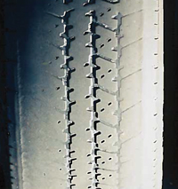
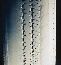
Tire wear in the center of the tread pattern tells you that the inflation patterns are too high. Too much pressure can cause the contact patch to shrink and the center of the tire to carry all of the load.


Under-Inflation Wear

Tire wear on the edges of a tire will typically indicate inflation pressures are lower than specified. When a tire is under-inflated, the contact patch grows and the load is carried by the outside edges of the patch.


Feathering

The indicator of excessive positive or negative toe angle is a feathering or scuffing that can be detected by stroking your fingertips across the edge of each tread bar or tread block. A feather edge on the inside of the tread bar indicates excess toe-in, while a feather edge on the outside of the tread bar indicates toe-out. Because the angle is affected by changes in camber and caster angles, it’s always the last angle to be adjusted during the wheel alignment process. In addition, any change in camber or caster angles will immediately change the toe angle. Toe angle geometry can also be greatly affected by changes in suspension height.

Scalloped

Cupped or scalloped dips appearing around the surface of the tread could indicate loose, worn, or bent suspension parts. Worn shock absorbers or unbalanced tires can also cause cupping, but the cupping would typically be more indicative of a concentric pattern. Shocks and struts are the most likely culprit because they provide damping force to control tire movement. When the tires move excessively, the scalloped pattern can appear. A lack of rotation can cause this condition.


Outer Edge Wear

Wear on the outer edge of a tire is rare these days, but it does happen. Positive camber, caster, and toe can lead to wear on the outer edge. If you see edge wear on one side, check the thrust and setback.

But, it should be noted, that the leading cause of outer edge wear on modern vehicles is over-enthusiastic cornering.


 Inner Edge Wear

Inner edge wear on tires is the most common problem most technicians see. The angles causing this type of wear are typically negative toe and camber. For parts, there are three component sources of the inner edge wear: bushings, springs, and loads.


  •  Bushings

Ozone, extreme temperatures, and other atmospheric issues tend to destroy rubber bushings and cause the alignment angles to change. Some vehicles have hydraulic bushings on the rear lower control arms. Some bushings will leak when they fail. When a bushing in the rear fails, the extra movement causes the wheels to toe out and the camber to go negative.

  •  Springs

As a suspension compresses and rebounds, the alignment angles change. Engineers tune alignment angles for a specific ride height to maximize handling and tire wear. If a spring can no longer support the vehicle, the alignment angles will suffer. Most engineers tune the suspension to toe out when the rear suspension compresses. This increases vehicle stability. But, it also causes the inner edge of the tire to wear. Springs are made of metal that is heat-treated but can still fatigue. This includes leaf, coil, and torsion bar springs. If you see a vehicle that needs considerable adjustments for camber on both wheels of the same axle, inspect the springs.

  • Loads

Loads in the rear of the vehicle will cause changes to the toe, caster, and camber in the front (and possibly the rear). The camber and caster will become positive in the front, and if the vehicle has an independent rear suspension, the camber will become negative and it will be toed out. This could lead to outside edge wear in the front and inside edge wear in the rear.

Chalk Test - You can visually determine if the tires are over or under-inflated with what is known as a chalk test. There are numerous YouTube and explanatory articles that can be found by searching for ‘chalk test’. All you need is a piece of chalk, an empty parking lot, the rig loaded as it would be going down the road and 15 minutes.


Use the recommended tire application, size, and load rating for your RV


    Look for the certification sticker on the door jamb of your LD; it contains information about tire size/type, recommended tire pressures, and tire weight capacities.


Light Truck is the somewhat confusing tire designation used for tires that are the appropriate size and application, i.e., designed for commercial or RV use, for your E-350/450 chassis.


Commercial grade/RV tires are often made of better grades of rubber, contain more UV and ozone protectants, and may have additional plies of polyester (or another material) in the sidewalls, and/or extra belts under the tread; these are usually steel 'mesh'. 


Use the appropriately-sized tire for your wheel.  Using even a slightly wider tire than the 225/75R/16E, i.e., a 2/5” larger 235/75R/16, reduces the amount of space between the duals.  Less space means excess heat build-up and possible blistering (and weakening) of the tires’ sidewalls.  


Also, 'non-spec' space between duals leads to possible contact between the duals when the tires flex during normal use; contact can cause the tires to 'scrub' and weaken the sidewall.  (And, the wider tire may not form a thorough seal when seated on the rim.) Never install a 16.5” (bead width) tire on a 16” rim, or vice versa.


Load rating E is the appropriate choice for the E-450 Ford chassis.  

Currently, Michelin, Goodyear, Bridgestone, Kumho, Toyo, and B.F. Goodrich are among several manufacturers that offer at least one LT/225/75R/16 E-load range tires that are appropriate for use on the E-450 chassis.  Check each manufacturer’s website for tire choices of the appropriate size, load rating, and application; the availability of tire models and applications changes frequently! 


Note:  The 'M+S' tire tread designation means that the tread grooves are wide and begin close to the outside edge of the tire; the wide tread grooves allow mud and snow to be thrown off more easily than from a narrow-grooved highway tire.  Sipes, usually hook-shaped or zig zag slits around the outer edge of the tire tread, provide increased traction on wet roads. M+S tires are not true snow tires; they are classified as all-season tires, suitable for a variety of road applications. 


        The most common causes of tire failures are overloading and underinflation.  


Weigh your coach, loaded and ready for the road, on all four 'axle corners'; the weight (of each corner of) your coach determines the inflation pressure(s) of your tires.  


All tires on the same axle should be inflated to the same pressure; if there is a weight discrepancy between the right and left side of the RV, air the tires to accommodate the higher weight.


Don’t exceed the maximum cold tire pressure, stamped on the tire sidewall (or the GVWR of your coach!)  If your weight indicates a tire pressure over 70 pounds, remove the rocks and scrap steel you are grossly overloaded.


     Load Rating Tables

Individual tire manufacturers’ websites offer tire care tips, application, size, load rating information, and inflation tables for their tires; check selections among LT225/75R/16E Examples of load rating tables.


https://www.michelinrvtires.com/reference-materials/load-and-inflation-tables/#/


www.goodyearrvtires.com/tire-inflation-loading.aspx


A closer look at a load range table. Using the Michelin XPS Rib as an example.


If the front axle weight is 4,600 pounds, then the proper inflation would be 65 pounds. (2,300 per tire x 2)

If the rear axle weight is 9,200 pounds, then the proper inflation would be 75 pounds.

(Note 4,600 + 9,200 is 13,800, the typical weight of a 26-foot going down the road with full gas, 2/3 water, and empty storage tanks)

Make sure you are typical and get it weighed.


TIRE MAINTENANCE


Inspect your tires regularly; don’t forget the inside duals!  Check the sidewalls for cracking, checking, bulges, tears or (excessively) scuffed areas.  (Also check the tire bead area for any gouges or shredded or missing rubber.)  Check the tread for tread depth, uneven wear, rocks or other road hazard debris, and any cuts or areas of missing rubber.


Tires deteriorate much more quickly when exposed to UV light and ozone in the air; wash tires with mild soap and water and rinse thoroughly.  Keep tires covered while the RV sits in storage or at a campsite.


Do not use tire dressings or vinyl/rubber treatments containing petroleum distillates, e.g., Armor All, on your tires or any vinyl or rubber surface; using these products can actually increase the rate of deterioration.  303 Aerospace Protectant is the good stuff!   https://www.goldeagle.com/brands/303-products/


RV tires should usually be replaced when the tires are about 5-6 years old, even if the mileage is low and the tread still appears good.  The sidewalls of RV tires are far more vulnerable to the effects of weight and wear than the tread, and time and exposure can deteriorate tires faster than use.


Tire Stores - You should seek one that normally handles larger vehicles. 


Install long brass valves; these valves make checking tire pressure and airing the tires much easier!  Search for dually tire valves or Borg tire valves.


http://yourtireshopsupply.com/category/796/dually-valve-kits is one source for these valves. These are NOT extensions, which can be dangerous.


Carry a reliable, accurate truck/RV tire pressure gauge that registers tire pressures up to about 100 pounds.  The pencil types are less accurate than numbered or digital read-out gauges.  Make sure that the gauge head is deep enough to allow a complete seal around the tire valve when you check the tire pressure.  Do not rely on the gas station or even tire shop gauges that are attached to the air hose; these are notoriously inaccurate.  


Make sure that the gauge selected is for truck/RV use, i.e.; the gauge needs to measure high enough pressures and be of a configuration that allows you to reach the valves to check the air pressure. I use an Accutire MS-4021B Digital Tire Pressure Gauge; see Amazon. Jayco is another quality vendor. A flexible hose is a plus.


Besides the gauge, other handy tire tools are a valve core tool, extra valve caps, an old (dull) screwdriver to pick rocks out of the tread, and a depth gauge measure.


Check your tires’ air pressure before each day’s driving; the tires have to be cold for an accurate reading.  'Eyeballing' does not substitute for using the gauge to verify correct tire pressures!


A laser digital thermometer is useful to quickly check tire pressure/temperature at a rest stop. You just walk around the rig and shoot all six tires noting the temperature. You will quickly learn what a normal temp is. The inside dual will always read a little higher than the outside.  80 to 120 degrees depending on ambient temp are normal.


Use metal valve caps to keep dirt, debris, and moisture out of the tire valves; these can damage the valve core and cause a slow leak.  The best 'air-through' valve caps are German-made V2B Alligators: 


https://shop.myerstiresupply.com/ERP2Web49/e2wItemMain.aspx?parentId=00083256


https://www.amazon.com/Alligator-V2B-Inflate-Through-Valve/dp/B014VCY3S2


Depending on speed, ambient temperature, and length of driving time, a tire can inflate to several pounds over its cold inflation (even exceeding the maximum) pressure.  This is normal; never bleed air from a hot tire.


Carrying a small 120V (or capable 12V) air compressor makes airing the tires much easier! 

400P-RV AutomaticPortable Compressor is an example.

https://www.viaircorp.com/portables/400p-rv-auto


If you use wooden or plastic blocks for leveling your coach, make sure that the blocks are wide enough and long enough to support the entire footprint of the tire!


https://trilynx.com/


Always block both rear duals when leveling the coach; never block just the outside dual.  


Air the spare to the maximum pressure listed on the sidewall.